
Influence Lines for Indeterminate Beams
Influence Lines for Indeterminate beams : Firstly Influence line diagram is a graph or a curve which depicts the different functions like support reactions, shear force and bending moment at a section etc; for different positions of unit load over the entire length of the structure.
Secondly Uses of Influence Line Diagram
1.To evaluate the values of shear force and bending moment of a structure subjected to a system external loads.
2.To evaluate the live load position for S.F, B.M, reactions etdi, in order to obtain the maximum value and to determine the maximum values of S.F, B.M etc.
thirdly Advantages of Influence Lines
1.influence line diagrams help calculate the shear force and bending moment of a structure at any section.
2.Influence line diagrams determine the position of the system of loads to obtain the maximum value of shear force and bending moment across the span of the structure.
3.Evaluating different functions (reactions, shear force, bending moment, when compared to manual method.
Indirect Model Analysis ;
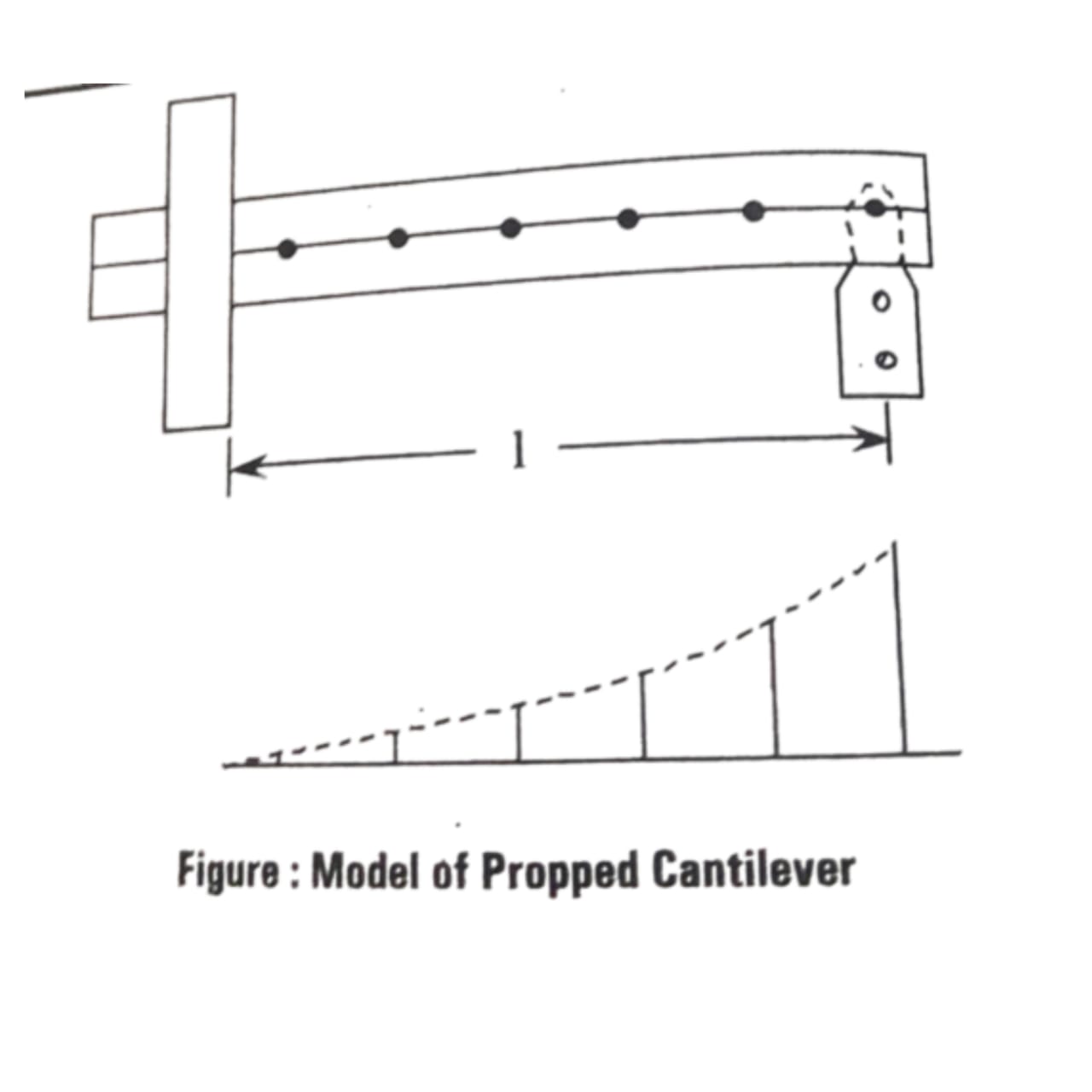
Indirect modal Analysis for influence line of indeterminate structures The principle said by Muller Breslau is applicable only for table model and for the known distances applied at certain points. This principle is not valid in case of experimental methods.
To get the influence line we have to measure the resultant distances and plot them.
Let us consider an indeterminate structure, Example: Proppéd cantilever.
Practical Considerations:
1.We need to apply a unit distance and measure the resultant distance.
2. If the model is 20 cm long then without breaking the strip there is no possibility of applying 1 cm distance.
3. It may require 1 mm more.
4. Within elastic limit, the distance shall be small enough to create stresses well.
5. By marking some targets on the model, plot the displaced configuration. It is measured by using micrometer microscopes over the target.
6. The targets should be sharp circles for accurate measurements.
influence line for support moment of continuous beam:
Let us consider a continuous beam ABCD which is shown in figure.
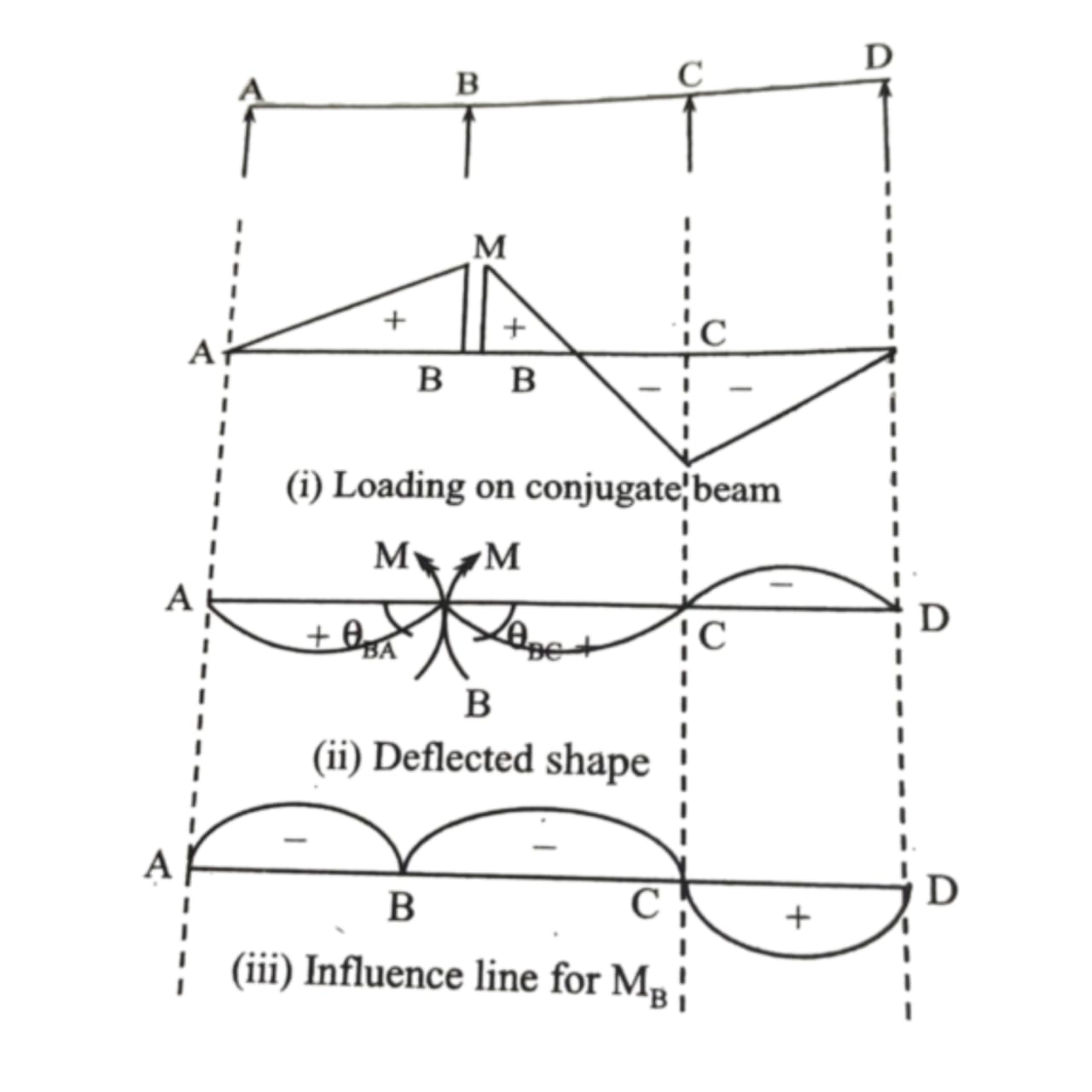
1. The influence line is drawn at point ‘B’ and moment ‘M is applied at point ‘B’.
2. The moment ‘M’ is applied such that ‘BA’ makes anti- clock wise and BCD makes clock wise.
3. 0 and 0 make unity by applying moment. BA
.. Influence line is obtained from deflected shape.
M=-y.
Finally conclude Influence Line for Shearing Force at a Point in SSB The influence Lines diagrams of a shear force at ‘C’ is as follow
