Up to now, it is studied only the projections of points and lines which are single dimensional. Rhe plane is a two dimensional (Fig. 6.24) the views are to be studied here in the first angle method as is included in SP-46-1998.
(A) PLANE PERPENDICULAR TO BOTH, THE PLANES.
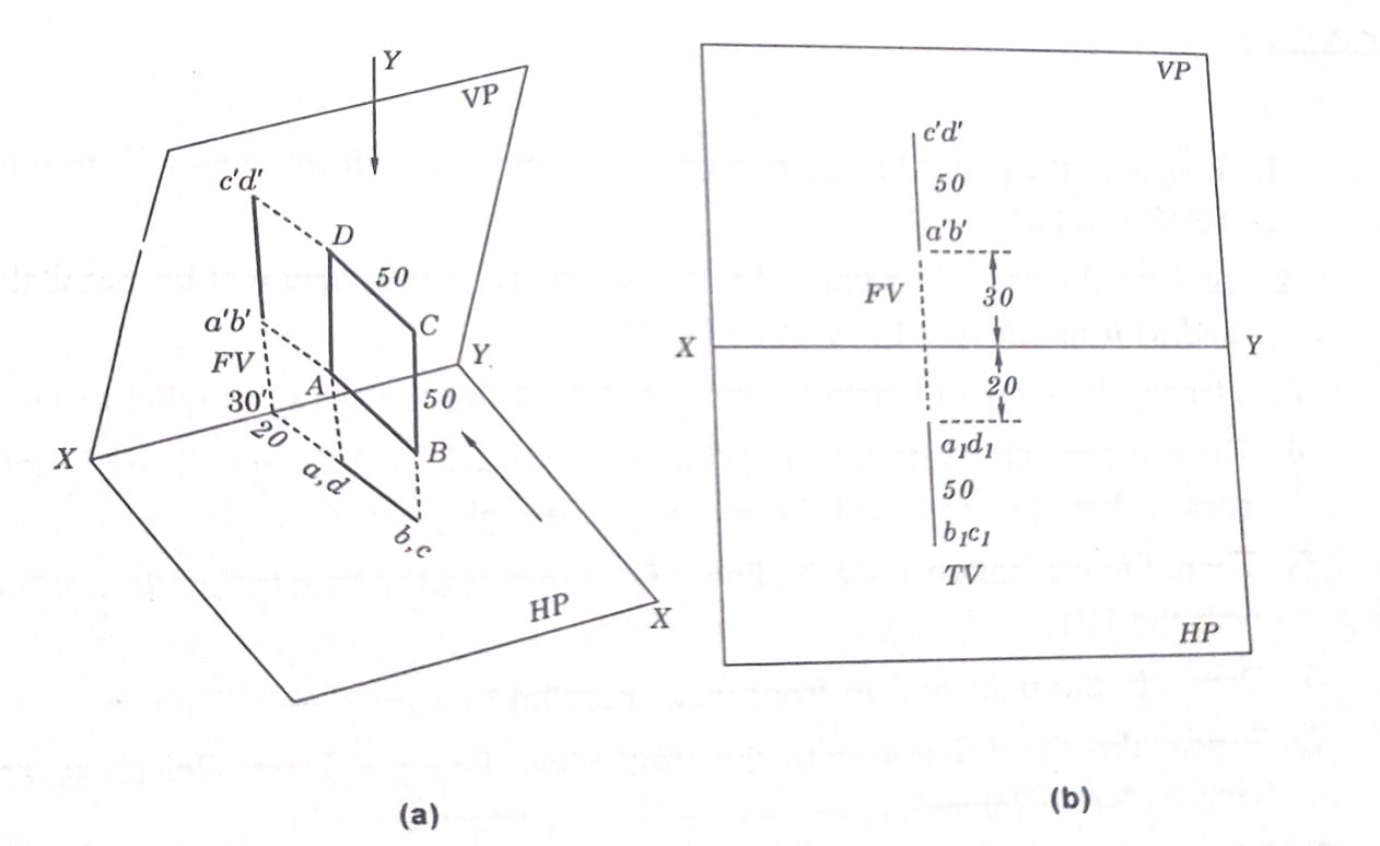
Q. Draw the projection of a square 50 mm side which is perpendicular to both VP and HP and the nearest side is 20 mm from VP and 30 mm above HP. Show the two views.
SOLUTION:
From Fig. (a) looking from x draw the front view and from y, draw the top view.
(B) PLANE PERPENDICULAR TO H.P AND PARALLEL TO V.P AND VICE VERSA.
Q.Draw the projection of a triangle 50 x 40 x 60 such that the longest side is parallel to V.P at 20 mm from the x-y line and lying on H.P and also plane contained by the triangle is perpendicular to H.P.
SOULTION:
From the Fig. (a) observing from X draw the front view and looking from “y” draw the top view as shown in Fig. 6.25 (b)
Q.Draw the front view and top view of a square 40 mm side which is equiangular and perpendicular to VP.
SOLUTION:
As the plane contained by the square is perpendicular to V.P, the top view shows full shape of the square as a-b-c-d and as the sides are equiangular to the VP, the top view (T.V) and front view (FV), are drawn as in Fig. (b) with reference to Fig. (a) looking from y and x respectively.
(C) PLANE PERPENDICULAR TO H.P AND INCLINED TO V.P AND VICE VERSA
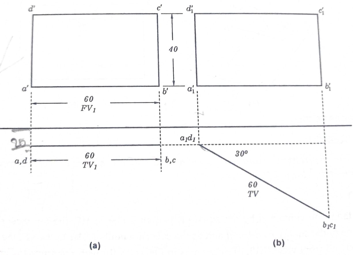
Q.Draw the projections of a rectangular plane 60 * 40 , the plane of which is perpendicular to HP and making an angle of 30 to the V.P. The longest side is lying on HP, where as its nearest point from V.P is 20 mm.
SOLUTION:
Draw the projections as per the following steps.
(1) Assume the plane of the rectangle is parallel to VP and draw the concerned F*V_{1} and T*V_{1} as shown in Fig. (a).
(II) Turn TV, to 30° to x-y line and mark a_{1}*d_{1} – b_{1}*c the same distance of T*V_{1} from x-y line.
(iii) Draw the projections from the Fig. (b) so as to cut the projections drawn from F*V_{1} and mark them as a_{1} – b_{1} – c_{1} – d_{1} which is the final front view (FV).
Note: When the plane is making some angle with VP, draw the full shape in VP and concerned view on HP and then after rotate the view (on HP) to the desired angle and project on to VP and similarly Vice-Versa.