COMPONENT PARTS OF A ROAD STRUCTURE

COMPONENT PARTSOFAROADSTRUCTURE 1. SUB GRADE: It is the top of the ground on which the foundation rests. If the subgrade is selected at higher level leads to the natural drainage. The top of the subgrade is 600 mm above the H.FL of that area
Functions:
1To support the road structure
2. To distribute the load over larger area.
3. To form a bed for the road at the designed level.
2. SUB BASE: It is the layer of locally available material laid over the subgrade. Material used may be sand, gravel, rubble. stabilized soil etc.,
If the subgrade and its drainage is good may be omitted.
Functions:
1. To protect the subgrade from rain
2. To improve the drainage
3. To reduce the cost of the pavement.
3. BASE COURSE: It is the layer between subbase and wearing course. It is made of good material like Hard Broken Granite metal and well compacted, It is important structural component and should be strong enough to bear the road traffic load.
Functions:
(1) To transfer the load from wearing course to sub base.
2.To the support for wearing course and avoid distortions on it.
3.To reduce the thickness of wearing course.
4. WEARING COURSE:This is the top most layer of the road which is in direct contact with the road traffic. It should be strong enough to take care of wearing effects of road traffic and impervious. If the water penetrates into wearing course life of road gets reduced.
Functions:
1.To provide smooth and stable road surface for road traffic
2 To drain away the rain water
3. It gives strength of the road structure.
WIDTH OF PAVEMENT (Or) CARRIAGE WAY:
The width of pavement depends upon the width of traffic lane and number of lanes. The carriage way intended for single line of traffic movement may be called as traffic lane. Width of lane is determined by considering max. width of vehicle and min – clearance required for safety
As per IRC max width of vehicle considered is 2.44m for its lane width considered is 3.8m for single lane. If the pavement having two or more lanes, the width of 3.5 m per lane is considered sufficient

SHOULDERS
The shoulders are provided on either sides of a road. The land width between outer edge of carriageway and the inner edge of formation width or drain (in case of cutting) is called shoulder. The shoulders are provided with earth surface or gravel or WBM or asphaltic and they should have sufficient load bearing capacity to support the loaded vehicles.
The functions shoulders are given below :
1. To give lateral stability to carriage way
2. To provide parking space in Emergency
3. To provide space for repair of vehicles
4. To provide space for overtaking vehicles.
The shoulders are also to be provided camber, for draining of rain water.

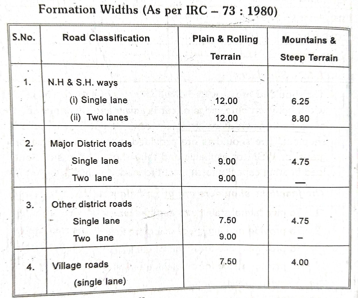
FORMATION WIDTH
Formation width or road way is the sum of width of carriage way and width of shoulders on either side. Formation width is the top width of road embankment or the bottom width of roadway in cutting excluding side drains.

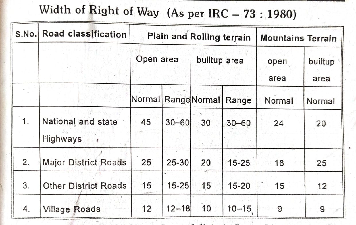
RIGHT OF WAY
Right of way is the area of land acquired and reserved for future development. It is desirable to acquire more land because the cost of adjoining land invariably increases after laying the road

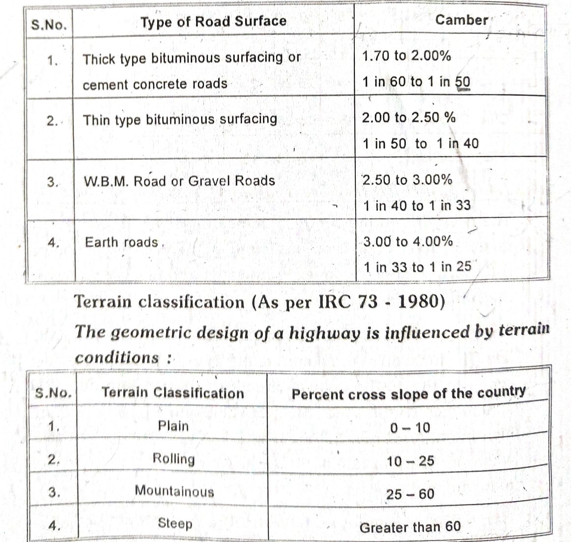
CAMBER (Or) CROSS FULL(Or) CROSS SLOPE
The rise given to the centre of the carriage way (crown) with reference to its edge is called “camber” The cross section of road surface shows convexity upwards and highest point on the curved surface is known as crown.
The shape of the camber may be parabolic, elliptic and straight line. The function of providing camber is to drain the rain water, separate the traffic in two directions and to improve the appearance of the road. Steeper values may be used when high intensity of rain fall areas and low values may be used where intensity of rainfall is low as well as the smoother the road surface.
Camber is expressed as 1 (vertical): n (Horizontal) or as a percentage (The camber with 3% for a 100 m width of road, the height of the crown will be 3m)
Disadvantages of Heavy Camber :
1. The shoulders on either side of a carriage way may get washed off due to increase of velocity of water.
2. Stability of high rise vehicles will be affected.
3. For high speed vehicles, the tendency to move towards edges increases (by skidding).
4. Road users uses more at the central portion of road and gets worn out

GRADIENT
The longitudinal rise or fall of road surface along its length is called as gradient and it is expressed as ratio 1 (vertical): n (Horizontal) or as a percentage.
Factors considered for deciding the gradient for a particular location are the drainage, the topography of the country, the nature of the traffic, the obligatory points, aiming least motive power etc
Types of Gradients: The major classification of gradients are of three types namely:
(a) Ruling gradient
(b) Limiting gradient
(c) Exceptional gradient
a) Ruling Gradient: These gradients may be used at isolated over in flat country, roads carrying a large volume of slow moving traffic, it will be desirable to adopt a flatter gradient of 2% from the angle of aesthetics, traffic operations and safety. Gradient upto the ruling gradient are to be adopted in normal course of design. The ruling gradients for different terrains are given in table
(b) Limiting Gradient: This gradient is used where the topography of a place compels this course or where the adoption of gentle gradients adds enormously to the cost. In such cases steeper than ruling gradient is to be provided for short length and flat or easier gradients to be provided on either side.
The limiting gradients for different terrains are given in table.
(c) Exceptional Gradient: These gradients are to be adopted only in very difficult situations such as approaches to cause ways and for short lengths not exceeding 100m at a stretch. In mountains and steep terrain, successive stretches of exceptional gradients must be separated by a minimum length of 100m having gentle gradient. Exceptional gradients for different terrain are given in table

SIGHT DISTANCE
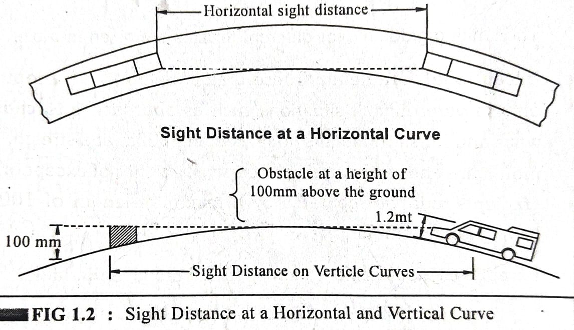
Sight distance/visibility is an important requirement for the safety of travel on highways. For this it is necessary that sight distance of adequate length should be available in different situations to permit drivers enough time and distance to control their vehicles, so that there are no unwarranted accident.
In the case of vertical curves the line of sight of the driver above the road is taken as 1.20m. The height of the object is taken to be at a height of 100mm or 0.10m above the road.
Types of Sight Distances:
1. Stopping sight distance.
2. Over taking sight distance.
3. Intermediate sight distance.
1. Stopping Sight Distance: It is the clear distance ahead needed by a driver to his vehicle to a stop before meeting a stationary object in his path.
It’s Minimum stopping sight distance is given by the sum of the
(i) Distance travelled during the perception and brake reaction time (Generally taken as 2.5 seconds – it depends on age, sex, alertness, visual capacity of driver, size and type of object, atmospheric visibility etc.
(ii) The braking distance (it depends on coefficient of longitudinal friction of the road, velocity of vehicle, type of condition of pavement wet or dry).
Stopping sight distance (SSD) is given by
S.S.D.=0.278 Vt+V²/254(1±0.01n)
Where
V= Speed of vehicle in KMPH
t = reaction time of driver sect
f =Design coefficient of friction 0.40 to 0.35
n= gradient in percent
2. Over Taking Sight Distance: It is the minimum sight distance that should be available to a driver on a two-way road to enable him to over take another vehicle safely.
Optimum condition for design is one in which the overtaking driver can follow the vehicle a head for a short time while he assesses his chances for over taking, pulls out his vehicle, overtakes the other vehicle at designed speed of the highway and returns to his own side of the road before meeting any oncoming vehicle from the OSD opposite direction travelling at the same speed.
Generally time required for overtaking will be 9 to 14 seconds.
3. Intermediate Sight Distance: It’s defined as the twice of the safe stopping sight distance. It is the experience that intermediate sight distance affords reasonable opportunities to overtake with caution.

