Helix is the locus of a point moving around and along the curved surface of a cylinder or cone with combined uniform angular velocity and uniform linear velocity about and in the direction of the axis.
The linear distance moved by the point in one revolution is called pitch or lead. If the point moves around and along the surface of a cylinder, the curve traced by it is called cylindrical helix, or simply helix, as shown in Fig.
PRACTICAL APPLICATION
The helical curve is widely used in mechanical engineering. The screw threads of V and squares types have helix profile. The helical grooves of square shape is widely used on cylindrical and drum cams, screw conveyors, etc., The springs of square or rectangular or round shapes are bent into helical shapes.
CYLINDRICAL HELIX
The following example shows the procedure of drawing a helix.
Q.Plot one complete turn of a cylindrical helix 50 mm diametre and 60 mm pitch. Also draw the development of the helical curve.
SOLUTION:
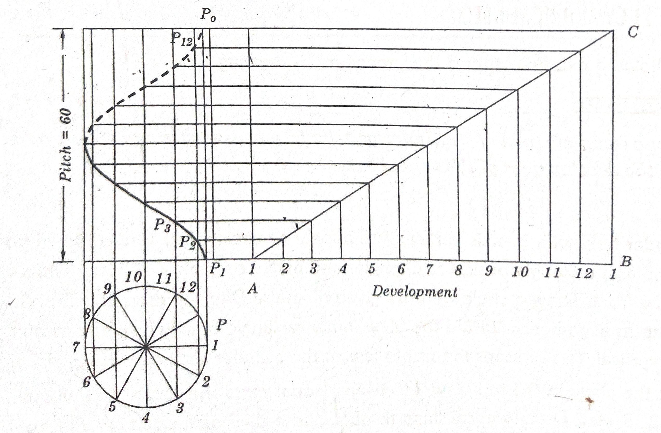
A cylinder held with its axis vertical, will appear as circle when viewed down from the top, and as a rectangle of side as diameter and height or pitch X diametre when viewed from the front. Draw a circle with the given diametre D to represent the Top View of a cylinder. In alignment with the top view, draw rectangle of side as diametre and pitch, being vertical, to represent the front view of the cylinder as shown in Fig..
Divide the circle in the top view into twelve equal parts and name the divisional point as 1, 2, 3 etc., Draw vertical lines through these divisional points to the front view. Divide the pitch also into the same number of (12) equal parts and name the division points 1′. 2. 3′ etc., Draw the horizontal lines through these division points. Initially, let the tracing point be at the left end of the horizontal diametre of the base of the cylinder. This position of the tracing point is indicated by the point P in the top view. Now let the tracing point move upward in the anti clockwise direction with combined uniform axial and uniform angular velocity on the curved surface of 1 the cylinder by 12 of a revolution. At the end of this angular movement, the tracing point on the curved surface of the cylinder in the front view, draw a vertical line through 1 to Intersect the horizontal line through 1′ at P1, Again, let the tracing point move further in the same anti clockwise direction with combined uniform axial and uniform angular velocity on the curved surface of the cylinder by 1/12 of the revolution. At the end of the second angular movement, the tracing point will have moved further up by a distance equal to 1/12 of the pitch. The second position of the tracing point will be at the division point 2 in top view. To get this second position of the tracing point on the curved surface of the cylinder in the front view, draw a vertical line through 2 to intersect the horizontal line through 2′ at P_{2} . Similarly, obtain other points P_{3} etc., as shown in Fig. 5.36. Passing through these points, draw a smooth helical curve. Since the tracing point moves on the rear side of the cylinder in the second half of the revolution, the helical curve passing through P_{0} to P_{7} is invisible and hence shown as an invisible curve of dashes.